
CWNA Chapter 2: RF Characteristics and Behaviors
Chapter 2 is an introduction to basic RF concepts.
Objectives
- Define/explain basic characteristics of RF and RF behavior
Electromagnetic Waves
- A wave is motion that travels through matter and space
- An electromagnetic wave is an oscillation that travels through space, and can even travel in a vacuum devoid of matter
- An electric field is the space in which an electrically charged object “feels” a push or pull (depending on whether the charge is like or opposite)
- The strength of an electric field is measured as the force induced on a unit of electric charge at any given point within the field
- A magnetic field is produced by the moving electric charge that is present around a magnet or in free space
- A changing magnetic field creates an electric field; this is key for the propagation of radio frequencies
- Radio frequency propagation describes the way in which waves move through space; electric fields create magnetic fields and vice versa
- Electromagnetic waves a combination of electric and magnetic fields propagating through space; the two fields oscillate perpendicular to each other
- A Radio Frequency (RF) system relies on electromagnetic wave theory to provide a communications system
- Modulation describes the manipulation of an electromagnetic wave to represent data
RF Characteristics and Behaviors
- Wavelength is the distance between two identical points on the wave (that are adjacent)…i.e. from peak to peak or trough to trough.
- Wavelength is a critical factor; dictates receiving antenna size and how the wave will interact with its environment
- Wavelength is related to the frequency and the speed of light; so, if you have frequency you can calculate wavelenght and vice versa.
- The hertz unit refers to the number of cycles a wave generates in a second
- kilohertz = 1,000 hertz, megahertz is 1,000,000 hertz and gigahertz is 1,000,000,000 hertz
- The following formula (where \(\lambda\) is wavelength in meters, \(f\) is frequency in hertz and \(c\) is the speed of light in a vacuum) can be used to calculate wavelength and frequency:
- The following simpler formulas can be used for approximations and are sufficient for the WLAN administrator:
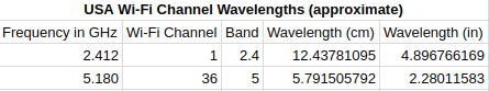
The following table shows Wi-Fi wavelengths for the first US channels available in 2.4 and 5 GHz. These were calculated using the approximations described above.
-
Note the wavelength for the 5 GHz channel is approximately half that of the 2.4 GHz channel; this greatly affects the receptivity of 5 GHz channels at greater distances
- Frequency refers to the number of wave cycles occurring in a certain window of time (usually 1 second)
- So, 1 kilohertz is 1,000 cycles of a wave in one second
- Wavelength, frequency and medium are interdependent; the higher frequencies will have the shorter wavelengths, whereas lower frequencies will have the longer wavelengths
- By using different frequencies, distinct RF connections can be made available in a given coverage area (or cell)
- If frequencies are used that are not sufficiently spaced apart, they will interfere with each other (like hitting 6 or 7 adjacent keys on a piano keyboard)
- Modulation describes the process in which a carrier is manipulated to represent meaningful information (or data)
- Frequency Shift Keying (FSK), altering the frequency to represent data, is used by some wireless systems (but not WLANs)
- Amplitude is the characteristic that describes “volume”;
- A “loud” RF wave with higher amplitude is easier to detect than a “quiet” one with lower amplitude
- A wave with greater amplitude is easier to detect at greater distance than one that starts with lower amplitude
- Noise Floor describes the continual backround RF noise present in a specific location, usually higher in 2.4 GHz and 5 GHz; high noise floor reduces the ability to achieve higher data rates
- An increase in amplitude will generally extend the “range” of an RF wave, but simply increasing output power will not necessarily be an improvement. If clients can’t match the output power, they might not be able transmit a signal to the access point. So, higher gain antennas or additional access points are usually a better solution.
- Amplitude Shift Keying (ASK) is a modulation technique involving changing the amplitude of a wave; this is used in WLANs
- Quadrature Amplitude Modulation (QAM) employs ASK and other modulation techniques
- Phase is a comparison between two RF waves; in-phase waves will strengthen each other and out-of-phase waves will cancel each other out
- Phase is measured in degrees, with 180 degrees being completely out of phase and 0 degrees being completely in phase
- In a practical sense for a CWNA, waves are usually simply in-phase or out-of-phase
- In-phase waves can increase the strength of a received signal, but it will never be stronger than the transmitted signal (since waves always weaken as they travel through space)
- Multiple-input-multiple-output (MIMO) takes advantage of the multiple paths a signal can travel to multiple antennas in slightly different locations in the transmitter and receiver devices; multiple paths produce waves that are usually a bit out of phase as a result of reflection or scattering
- Phase Key Shifting (PSK) shifts the phase of waves as a modulation technique; 802.11 WLANs use both PSK and ASK
RF Behavior
- RF Signals are a created by RF waves that have been modulated to contain/represent information
- The gain is positive amplitude difference between to RF signals (can be intentional or unintentional)
- Amplification increases an RF signal’s amplitude (thus resulting in gain); can be either passive or active
- Active gain occurs when an amplifier is placed in-line between an RF signal generator and the propagating antenna
- An intentional radiator is the point in the radio system where the system is attached to an antenna
- Passive gain does not describe an increase in the amplitude of the signal sent to the intentional radiator, but instead describes an increase in amplitude of the signal in a favored direction by the focusing or directing of output power
- Antennas provide passive gain; they don’t increase the total output power, but focus it in a specific pattern
- Loss is the negative amplitude difference between two RF signals (can be intentional or unintentional)
- Intentional Loss intentionally reducing the amplitude of the output RF signal; can be required to comply with requirements in a regulatory domain or a design specification
- Attenuators used to create intentional loss in an RF signal (usually placed between the AP and the antenna)
- Natural Loss is loss that occurs due to the normal process of RF propagation (involving spreading, reflection, refraction, scattering, diffraction and absorption)
- Reflection occurs when an RF signal bounces off of a smooth and non-absorptive surface; this changes the direction of the signal
- Similar the affect observed when shining a light in a mirror
- RF signals will reflect off of objects that are smooth and larger than the waves carrying signals (5 GHz waves are approx 5 cm and 2.4 GHz waves are approximately 13 cm); metal objects are typically reflective
- Reflected signals will almost always be weaker after reflection, since some energy is absorbed by the reflecting material
- Multipath results from reflections and scattering, and occurs when multiple signals traverse different paths to the same receiver
- Single-input-single-output (SISO) systems have difficulty with multipath, so antenna diversity was introduced to help deal with this problem
- Antenna Diversity involves multiple antennas connected to the same radio receiver, and utilizes the antenna with the best reception of a signal to process the communication
- Multiple-input-multiple-output (MIMO) systems take advantage of multipath to send and receive multiple spatial streams of data at the same time (MIMO is utilized by 802.11n, 802.11ac, and will be utilized by the forthcoming 802.11ax)
- Refraction is the changing in speed and bending of an RF signal as it passes through media of different densities
- The refraction index is a measurement of how much refraction will occur when a signal passes through a specific medium
- Usually, refraction affects outdoor site-to-site links rather than connections within a building
- Diffraction occurs when a wave changes direction or intensity when it passes by the edge of an obstacle (think of ripples in a still pond passing around a stick)
- Typically caused by buildings, hills, or other large objects in an RF signal’s path; elevator shafts are a common cause of diffraction inside buildings
- RF Shadow describes the area that may no longer be able to effectively perceive the RF signal as a result of diffraction
- Scattering results from and RF striking an uneven surface (or one with inhomogeneities); the signal is reflected into multiple signals less significant than the original
- Caused by smog, rocky terrain, leafy trees, chain link fencing, rain or dust
- Absorption is the conversion of RF energy into heat; occurs because the molecules in the medium through which the RF energy is passing are not able to move fast enough keep up with the electromagnetic waves
- Drywall, wood, and humans are common causes of RF absorption
- Microwave ovens operate in 2.4 GHz and work off of this principal; they work because of water molecules in foods that have moisture in them
- Microwaves are a good example of absorption and refraction - the food is heated by absorption, and the generated electromagnetic waves are kept inside the microwave by reflection
- Drywall tends to have an absorption rate of 3 - 5 dB, while concrete walls are usually in the 6 - 15 dB range
- Voltage Standing Wave Ratio (VSWR) is the measurement for mismatched impedance (return loss) in an RF system, stated as an X:1 (read “X to one”) ratio
- A lower first number indicates a better impedance match
- A hepful analogy is a water pump attached to different size pipes; ideally, the pipes should be the same size
- Impedence describe the amount of resistance in an electric circuit (rated in ohms - \(\omega\)); typically WLAN equipment uses 50 ohm components
- Mismatched components can cause damage to equipment, so all components (connectors, cable, etc.) should have the same impedence rating
- VSWR of 1.5: is a good match (4% loss), 1.0:1 is impossible with current technology
- VSWR of 6.0:1 is a 50% loss in power
- VSWR 10:1 is unacceptable; most power is lost
- Return Loss a measurement (in dB) of the ratio between the forward current (the incident wave) and the reflected current (reflected wave)
- Occurs when VSWR is greater than 1.0:1 (which is always the case); some power loss occurs due to backward reflection of the RF signal within a system
- Typically, significant return loss will cause the output power at the intentional radiator to be significantly less than the output power generated by the transmitter
- To avoid this, use avoid impedance mismatches in the entire chain–from radio to antenna; ensure all equipment has the same ohm rating (usually 50 ohm)
- Perfect Open describes a situation in which cabling is not connected to an antenna
- Insertion Loss, often stated as dB loss per foot, is loss incurred by inserting an object like a cable or connector in the path of the RF signal between a source and intentional radiator
- Wave Propagation describes the way in which RF waves move through an environment
- Signal strength becomes weaker and weaker as distance from the intentional radiator increases, eventually becoming indistinguishable from the noise floor
- Free Space Path Loss (FSPL or FSL) describes the fact that a RF signal wave front weakens as the signal disperses; the wave front becomes larger as the signal moves away from the antenna and loses amplitude because energy is spread over a larger and larger area
- Signal Dispersion desribes the broadening of an RF signal wave front
- Beam divergence is another term describing the broadening of the wave
- Beam divergence can be calculated by: \(Divergence = (D1 - D2) / L\).
- FSPL can be calculated as:
$$FSPL = 36.6 + (20log10(F)) + (20log10(D))&&
- F is frequency in MHz and D is path length in miles; for kilometers change 36.6 to 32.4
- This formula will not appear on the CWNA exam, and is easily estimated using the 6 dB rule (covered in the next chapter…for each doubling of distance there is an amplitude loss of ~6 dB)
- The 6 db rule has its roots in the inverse square law; thus, an increase of 6 dB in the signal doubles the distance at which the signal is usable (and the reverse)
- Multipath is created when signals bounce around in a particular environment due to reflection, refraction, diffraction and scattering; multiple signals are observed at the receiving antenna within nanoseconds of each others’ arrival
- Can occur outdoors, but occurs very frequently indoors; as a result, many APs now have multiple antennas and utilize MIMO capabilities to take advantage of this phenomenon
- Delay Spread describes the time delta between when the first and second signals arrive in a multipath scenario
- With sufficiently small delay spread, multipath can offer an advantage; issues can result if delay spread is too large and signals are observed out of phase at the receiver
Notes are based on the Certitrek Certified Wireless Network Administrator Official Study Guide (Tom Carpenter and Mitch Dickey).
Written on May 8, 2018